 ar
ar bg
bg hr
hr cs
cs da
da nl
nl fi
fi fr
fr de
de el
el hi
hi it
it ko
ko no
no pl
pl pt
pt ro
ro ru
ru es
es sv
sv tl
tl iw
iw id
id lv
lv lt
lt sr
sr sk
sk sl
sl uk
uk vi
vi et
et hu
hu th
th tr
tr fa
fa ms
ms hy
hy ka
ka ur
ur bn
bn mn
mn ta
ta kk
kk uz
uz ku
ku
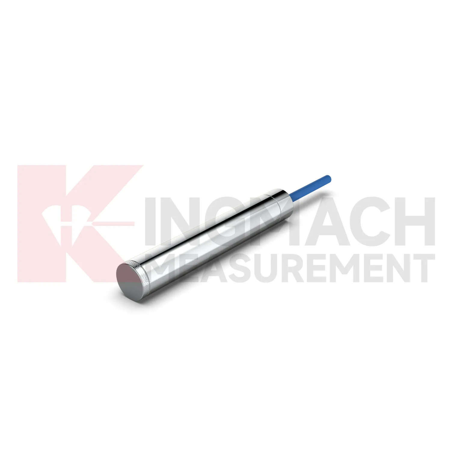
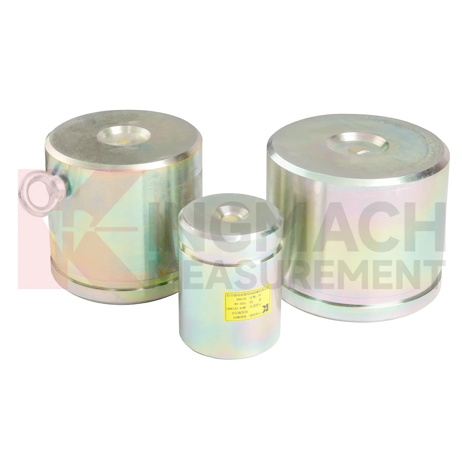
load cell connection diagram
Kingmach load cell connection diagram covers more than one mechanical form, which matters because force does not enter every structure the same way. The solid load cell JMZX-35XXHAT is listed for 1000 kN to 10000 kN with 0.1 kN resolution and 0.5%FS precision. The same product file gives a -30°C to 80°C working temperature range, 20 to 50%F.S. range overload, and 300 to 400%F.S. failure overload. It also stores model, number, calibration coefficient, pressure value, zero parameter, and temperature correction data. These points make it better suited to compression load checks such as pile load testing, bridge pier support measurement, and heavy structural bearing work. The instrument is part of a larger Kingmach monitoring catalog that includes displacement, settlement, tilt, pressure, water level, and acquisition products. For procurement, the practical review should cover capacity margin, bearing surface geometry, calibration documents, expected temperature range, overload exposure, and whether the readings will be taken locally or fed into an automated system. Kingmach also presents the product family alongside project areas such as bridges, dams, tunnels, subways, slopes, buildings, subgrades, wind towers, and foundation pits. That makes the specification less abstract: each model can be matched to a known load path and a known field environment before ordering.
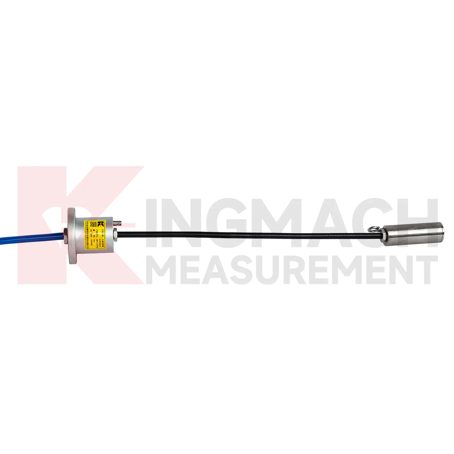
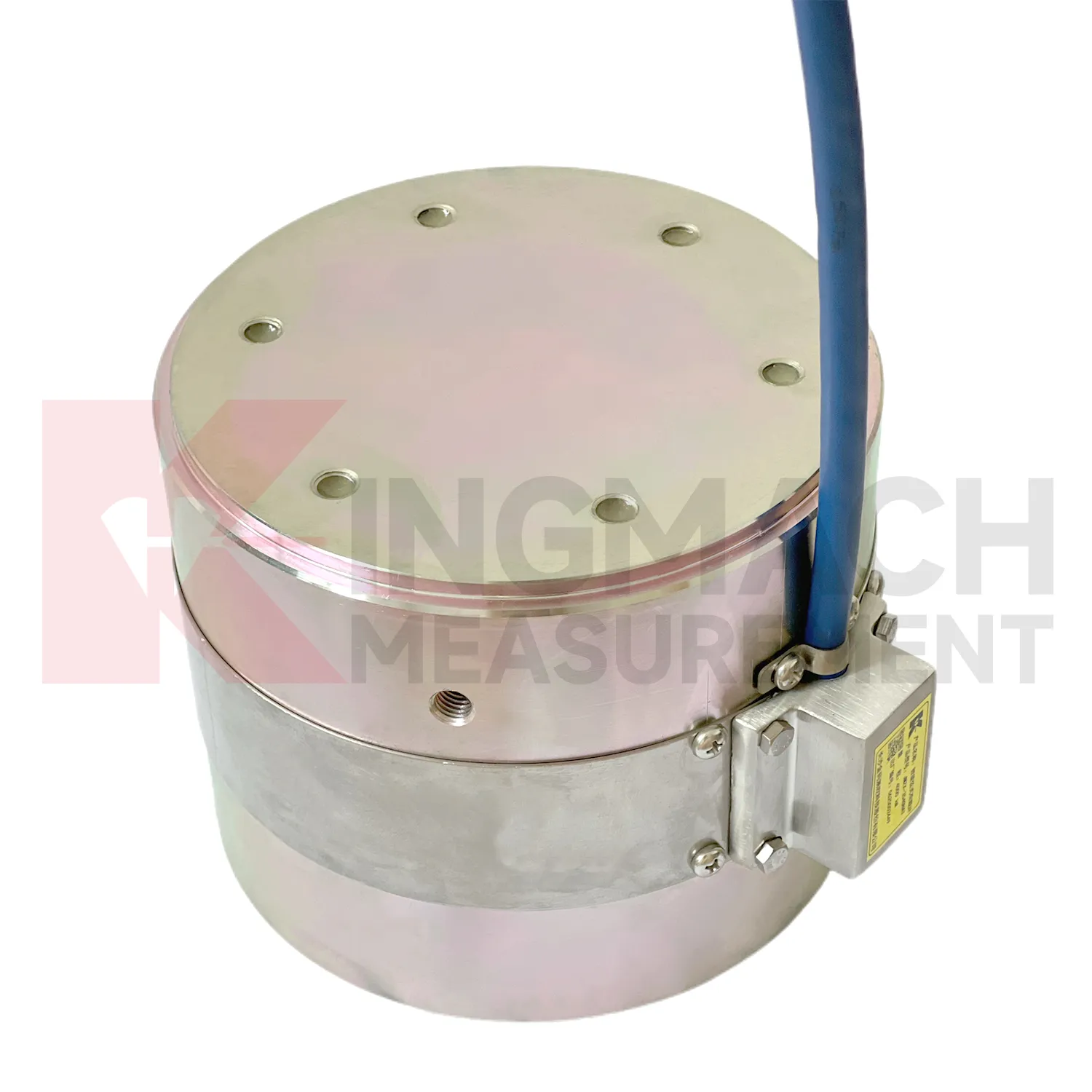
Application of load cell connection diagram
In pile load testing and bearing capacity verification, load cell connection diagram helps track applied force, load stages, unloading response, and residual behavior. The common problem is uncertainty around whether the applied load is centered and whether the recorded value matches the actual force passing through the test system. Kingmach solid load cells such as JMZX-35XXHAT list 1000 kN to 10000 kN ranges, 0.1 kN resolution, and 0.5%FS precision, with overload information listed as 20 to 50%F.S. range overload and 300 to 400%F.S. failure overload. These figures suit heavy test work when capacity margin must be checked before the sensor is installed. During the test, the record should include each loading step, hold time, unloading step, zero check, temperature, and any change to the bearing arrangement. Pairing the load record with settlement readings gives a clearer view of pile response. After the test, the documented calibration coefficient and instrument identity help keep the acceptance file defensible. Test reports should also record jack pressure, settlement response, load rate, hold duration, and any adjustment to the reaction system. These records help engineers identify whether an unusual load value came from the pile, the loading setup, or the measurement chain.
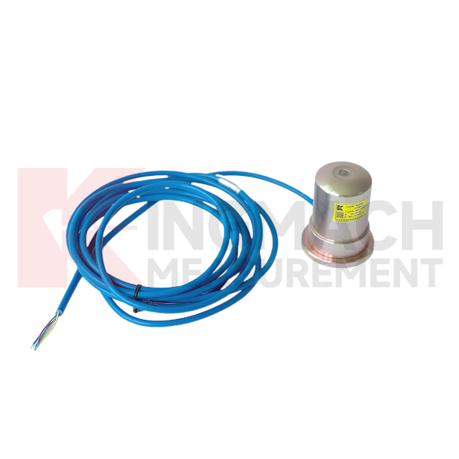
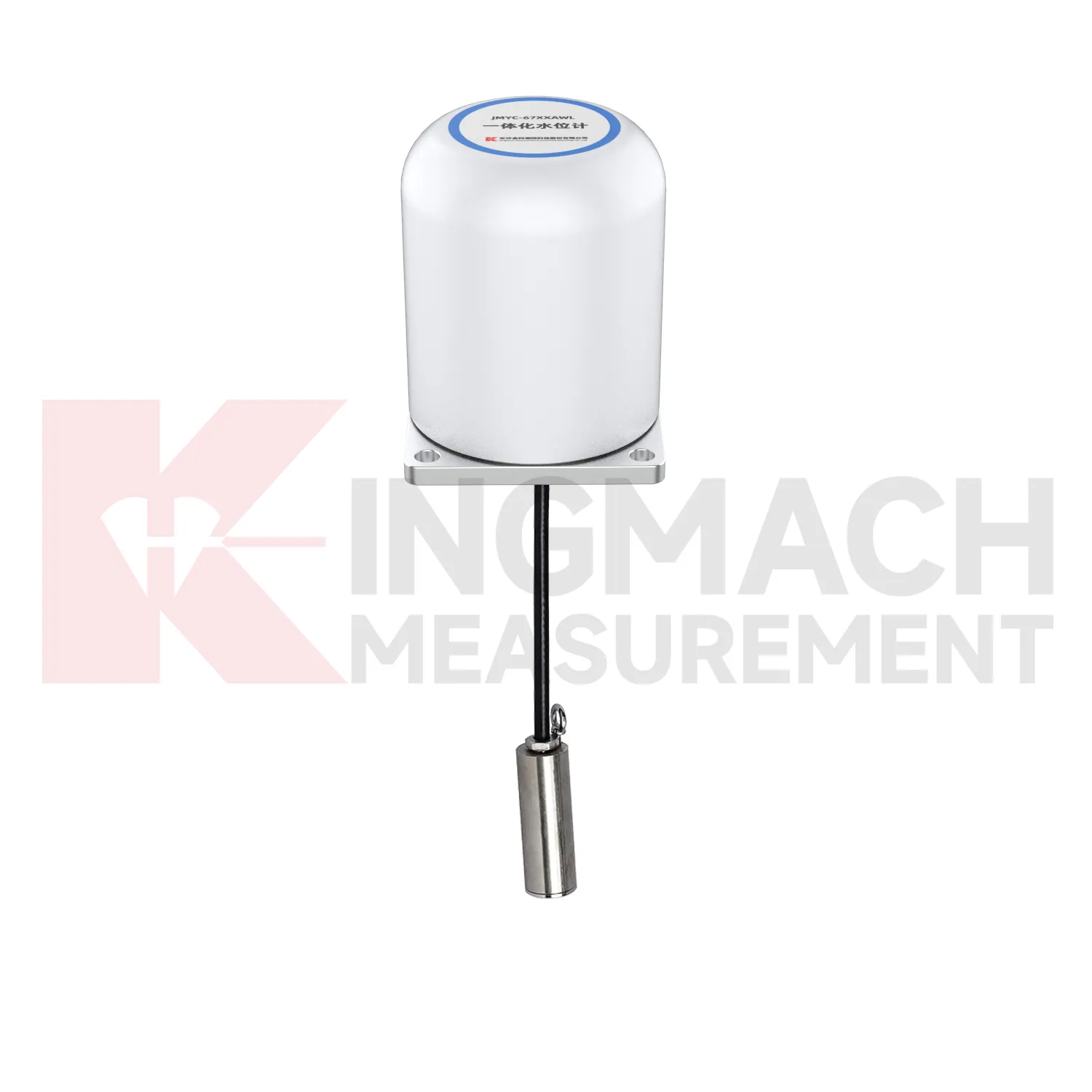
The future of load cell connection diagram
Future load cell connection diagram use will depend on cleaner data pipelines, not only stronger metal parts. Kingmach's smart load cell features, including digital output, long distance transmission, anti-interference performance, temperature correction, and stored parameters, already point toward connected monitoring. In the next few years, more projects are likely to use edge acquisition units that check whether a reading is plausible before it reaches the platform. A sudden force jump can be compared with temperature, cable condition, nearby displacement, and recent construction events. AI based warning tools may help sort routine fluctuation from patterns that deserve inspection, but they will only work when the instrument record is consistent. That places more value on channel naming, calibration certificates, zero checks, installation photos, and maintenance logs. The product direction is therefore practical: robust sensing at the point of load, reliable transmission from difficult sites, and software that helps engineers review trends without losing the original measurement context.
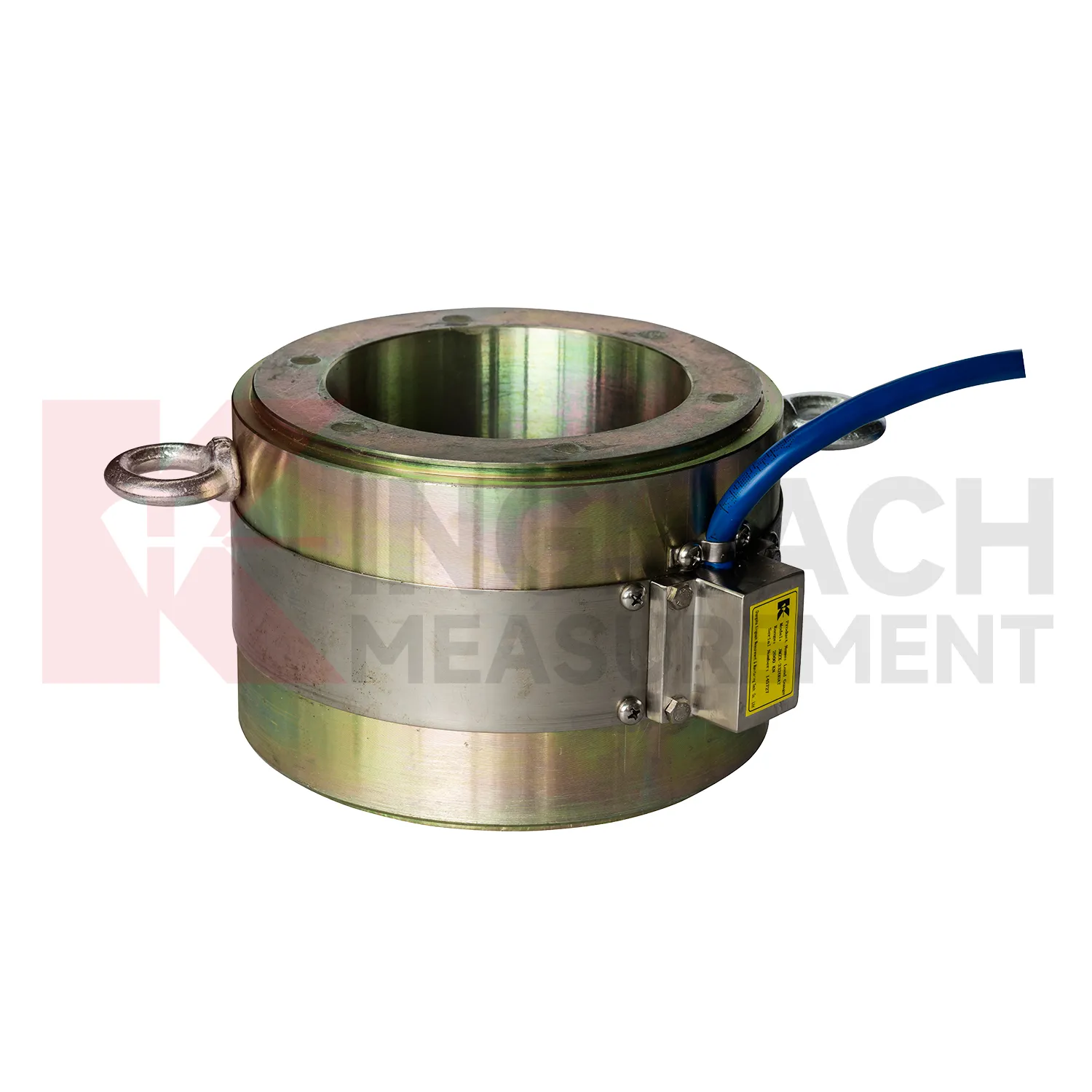
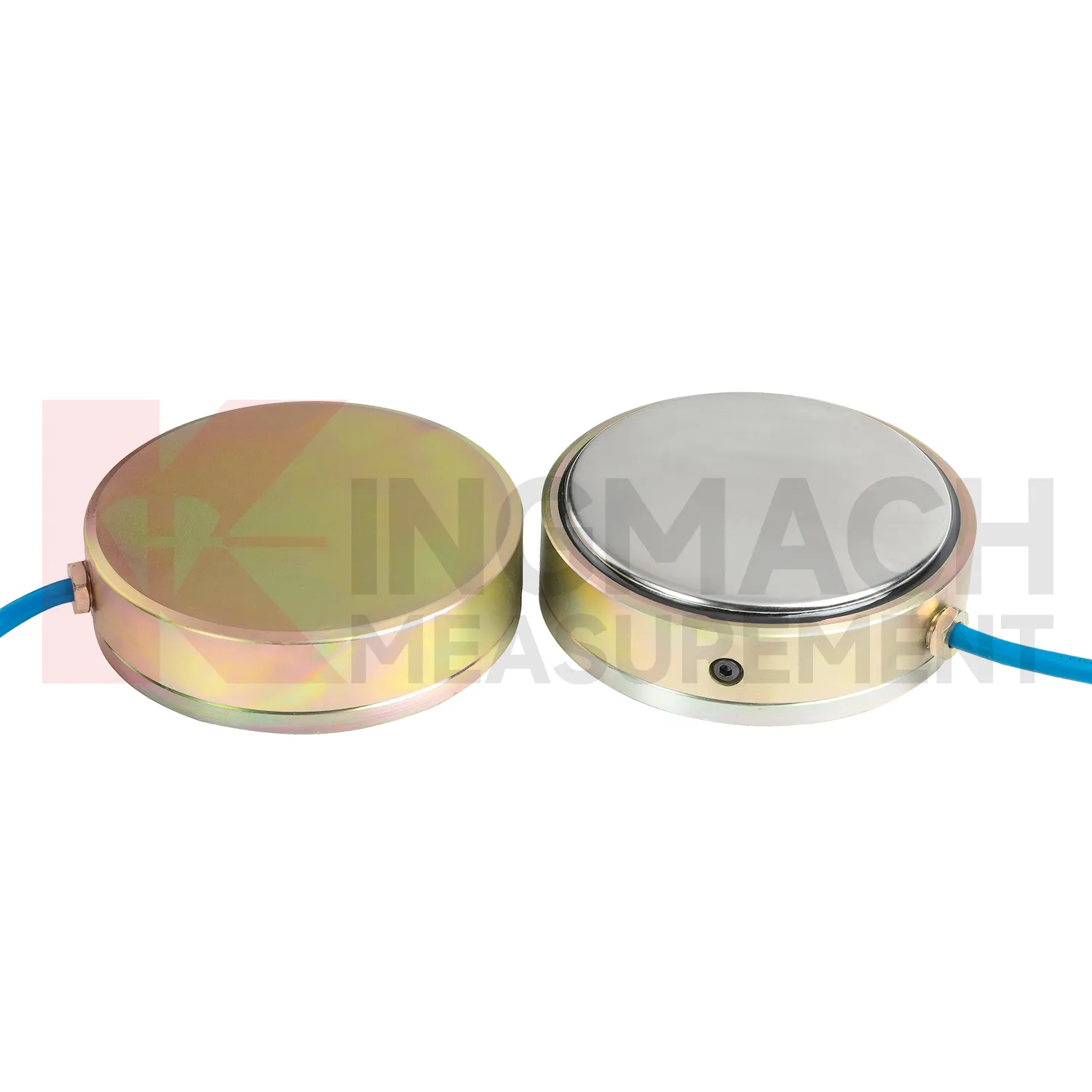
Care & Maintenance of load cell connection diagram
For load cell connection diagram installed in foundation pits or tunnels, the maintenance routine must fit a fast changing site. Axial force meters may cover 200 kN to 3000 kN with 0.5%FS accuracy and direct kN display, while earth pressure cells may cover 0.3 MPa to 8 MPa with 0.001 MPa resolution. During installation, confirm that steel support surfaces have enough thickness and strength, and add buffer plates where stress concentration is possible. Protect the sensor body and cable from equipment impact, cutting, concrete splash, and standing water. During excavation, check readings after each major stage rather than waiting for a fixed calendar date. If a channel becomes unstable, inspect the cable route, connector, readout, and temperature condition first. Long term points should have waterproof labels, photo records, and clear channel mapping. Sudden changes should be compared with wall movement, settlement, water pressure, and site work before any conclusion is recorded.
Kingmach load cell connection diagram
load cell connection diagram belongs at the point where a drawing stops being a guess and the structure begins to report what is really happening. In Kingmach engineering monitoring, force data is used around bridge cables, anchor heads, pier bearings, pile tests, retaining systems, and temporary steel supports. The reading is not only a number in kN. It is a record of where the force sits, when it changed, and which construction or service condition caused that change. A practical monitoring plan often pairs force with displacement, settlement, tilt, temperature, water pressure, or rainfall, because load rarely moves alone. For procurement teams, the useful questions are direct: capacity range, accuracy, installation space, cable route, waterproofing, calibration record, and data acquisition method. When these items are settled before site work starts, the same instrument can support acceptance checks, construction control, and later maintenance decisions without forcing engineers to rebuild the data story. That early planning also keeps later reports from mixing force trends with installation doubts.
FAQ
Q: Can load cell connection diagram be used for soil pressure or retaining wall pressure? A: Yes, pressure related models such as earth pressure cells are used where the measured value is contact pressure rather than direct member force. Q: What ranges are listed for Kingmach earth pressure cells? A: The JMZX-50XXAT/ATM family lists 0.3 MPa, 0.6 MPa, 1 MPa, 2 MPa, 4 MPa, 6 MPa, and 8 MPa ranges. Q: What accuracy and resolution are listed? A: The product file gives 0.001 MPa pressure resolution, 0.5%FS pressure accuracy, and ±0.5°C temperature accuracy. Q: Where are these readings useful? A: Foundation pits, dams, slopes, retaining walls, embankments, tunnels, and buried structures. Q: What maintenance issue is most common? A: Cable damage, water entry, channel confusion, and poor installation records cause many field doubts.
Reviews
Robert Taylor
The weir flow meter is well-built and delivers accurate measurements. Great value for water management applications.
Andrew Lee
The visualization software is intuitive and powerful. It helps us analyze monitoring data efficiently.
Latest Inquiries
To protect the privacy of our buyers, only public service email domains like Gmail, Yahoo, and MSN will be displayed. Additionally, only a limited portion of the inquiry content will be shown.
Mia***@gmail.comNetherlands
Dear team, we are interested in your readouts & data loggers compatible with multiple sensors. Do yo...
Charlotte***@gmail.comUnited Arab Emirates
Hi, we require instrumentation cables suitable for harsh environments. Could you advise on specifica...